We use cookies to Improve your online experience. By continuing browsing this website, we assume you agree our use of cookies.
Home > 200A HV Master BMS Control Box

200A HV Master BMS Control Box

Battery Control Box

200A HV Master BMS Control Box

The 200A high voltage master BMS is the switching and control layer of a battery cluster: one enclosure that carries the main circuit breaker, the pre-charge circuit, current measurement, insulation detection and the cluster control unit. If you are specifying a battery control box for a cabinet or container build, it sits between the cell strings and the PCS and keeps the main circuit in a known state. It is also the layer a battery bms architecture relies on to report cluster status upward over CAN or RS485, so the converter and the site EMS read the same data.

200A HV Master BMS
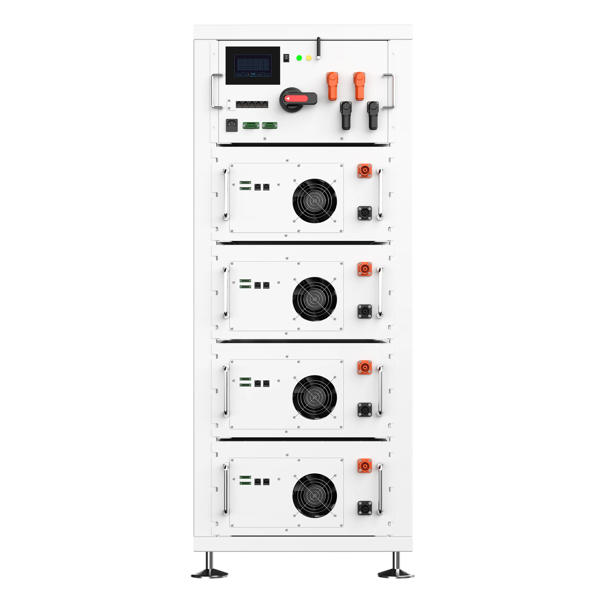
ESS-HV-BC250200A closed unit — 200A main circuit with a built-in BCU.
Hardware

Inside the 200A Control Box

This is a switching and protection assembly, not a bare circuit board. Each numbered block below matches a component in the unit you receive.

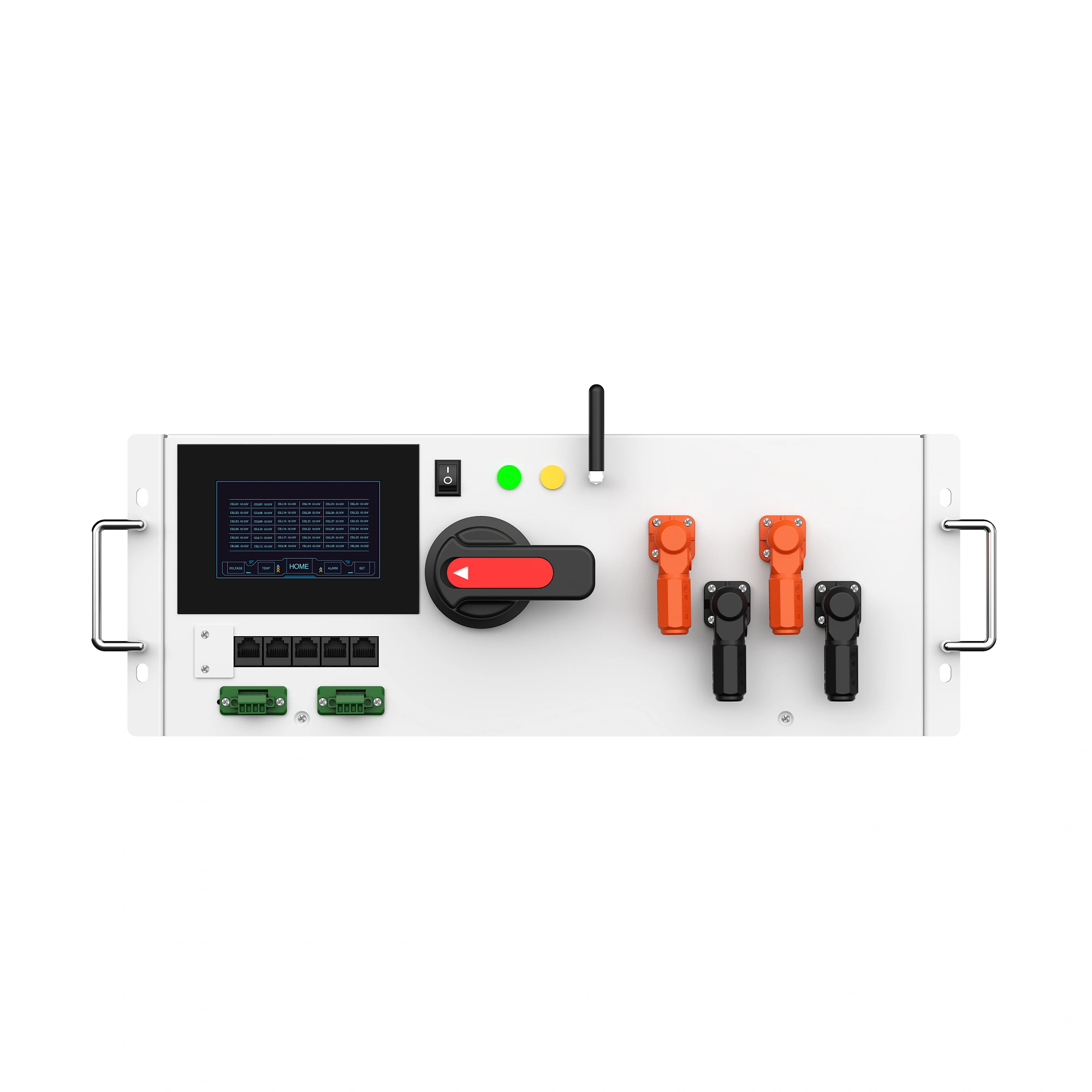
200A high voltage master BMS control box hardware layout
200A HV master BMS — the switching, pre-charge and control assembly in one enclosure.

Buyer decision: the 200A breaker and the 250A contactors define the continuous-current ceiling of the whole cluster — compare them with your inverter's charge and discharge current before you commit to this rating.

Architecture

Where It Sits in the Cluster

Cell stringsSeries-connected cells
→
BMU / slave boxesCell voltage and temperature
→
Control box (BCU)Switching, protection, cluster data
→
CAN / RS485Daisy-chain link
→
PCS / EMSConversion and site control

The control box is one link in a chain, not the whole chain. Cell strings feed the BMU or slave boxes, which measure cell voltage and temperature. Those units report upward to the control box, where the built-in BCU aggregates the cluster, runs protection logic and holds the main circuit open or closed. From there a single CAN or RS485 path carries cluster status to the PCS or the site EMS. The control layer is a per-cluster device, while the slave side scales with cell count — so if your design already includes a master BMS with an integrated BCU, adding a second control layer only duplicates protection and wiring.

200A high voltage master BMS cluster control unit
Fit gate

Will the 200A Unit Fit Your Cluster?

Two numbers decide the purchase: current and voltage. Check both before you add the unit to a project.

Main circuit200A
Working windowDC 120–750V
DC contactors250A charge / 250A discharge
Current sensor50A · ±0.2%
CommunicationCAN + RS485
  • Add up your string voltage at full charge — the pack must stay inside the DC 120–750V working window with usable margin.
  • Compare continuous charge and discharge current with the 200A main breaker and the 250A contactors.
  • Check that the pre-charge path (30A contactor with a 50Ω resistor) suits the input capacitance of your PCS.
  • Confirm the 150A main-circuit fuse matches the protection plan for your cluster.
  • If 200A is well above what your cluster carries, size down to the 100A master BMS instead of over-specifying.

Working voltage window

Below window
DC 120–750V operating range
Above window
120V750V

⚠Confirm string voltage before ordering. The unit is specified for a DC 120–750V working range — verify your final configuration against it.

Integration

Communications and Protocol Hand-Off

The wiring is standard; the protocol is a project detail. Separate the two before you place an order.

Supported on this unit

  • CAN interface
  • RS485 interface
  • RJ45 CAN communication interface
  • Daisy-chain support to battery management modules
  • Communication with PCS systems
  • Built-in BCU for cluster control, protection and data

Confirm before order

  • Protocol profile your PCS or EMS expects
  • Connector requirements for power and signal
  • Installation conditions in the cabinet or rack
  • Final configuration for the project
  • Quantity and lead time

“Please confirm the final configuration, communication protocol, connector requirements and installation conditions before mass production.”

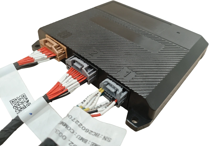
200A high voltage master BMS communication interfaces
Scenario fit

Match the Box to Your Build

Four common builds, each tied to a confirmed product fact and the decision it forces.

Cabinet retrofit behind an existing PCS

Product factRJ45 CAN interface and RS485, with daisy-chain support for communication with battery management modules and PCS systems.

Buyer decisionName the protocol your converter speaks when you request the quote — a matching physical port does not guarantee a matching protocol.
Container or C&I cluster with heavy current

Product fact200A molded case circuit breaker, 250A charge and 250A discharge contactors, and 0–200A energy storage connectors.

Buyer decisionSize your lugs and cable schedule to the connector family you order, then confirm continuous current stays under the breaker rating.

Long strings near the top of the window

Product factDC 120–750V working range with a 50A current sensor at ±0.2% accuracy.

Buyer decisionMeasure the full-charge string voltage of the exact configuration you will build and keep headroom at the top of the range.

Integrator standardising an OEM design

Product factOEM and ODM custom projects are supported, with CE, RoHS and FCC documentation available per product or project requirement.

Buyer decisionRequest a project quote with volumes and the documentation list your customer's approval process will ask for.

Scope

What Ships, What Does Not, and How to Quote

Supplied with the unit

  • 200A molded case circuit breaker for cluster circuit control
  • 250A DC charging contactor and 250A DC discharge contactor
  • Pre-charge circuit: 30A contactor with a 50Ω resistor
  • 150A main-circuit fuse and insulation detection
  • 50A current sensor at ±0.2% accuracy
  • 120W / 24V switching power supply
  • Built-in BCU plus BMS power control switch and indicator
  • EU warehouse as the listed shipping origin

Not included unless quoted

  • Battery cells or a complete battery cluster
  • PCS / energy storage converter
  • External battery and PCS power cables
  • External communication cables
  • Energy storage cabinet or rack
  • LCD display unless specified
  • External IoT monitoring equipment
  • Site installation and commissioning service

Project pricing, OEM/ODM support, confirmed lead time

Send your string voltage, continuous current, PCS protocol and cabinet layout. You get a configuration matched to the 200A unit, a quantity-based price and a lead time confirmed by order quantity.

Related Reading

Three notes to help clarify product requirements before contacting the supplier.

What Does a Battery Control Box Do in High Voltage Battery Clusters?

A high voltage battery cluster needs a control box that converts module and cluster data into control actions between the cell modules and the PCS.

Read article

CAN and RS485 Wiring for High Voltage BMS and PCS Integration

Commissioning teams often find that a working CAN or RS485 port still leaves the PCS, EMS, and battery cluster speaking different languages.

Read article

What Does a Master BMS Control in a Battery Cluster?

A master BMS controls cluster-level switching, protection, and external communication, while cell-level measurement and balancing are handled by other parts of the system.

Read article

Frequently Asked Questions

What is a 200a high voltage master bms control box?

It is a single enclosure that consolidates the cluster's main circuit protection and control: a 200a molded case circuit breaker, 250a charge and 250a discharge contactors, a pre-charge circuit with a 30a contactor and 50ω resistor, a 150a fuse, a current sensor at ±0.2% accuracy, a 120w/24v power supply, insulation detection and a built-in bcu.

What voltage range does this unit work in?

The product description lists a dc 120–750v working range. confirm your string voltage at full charge against that window, with margin, before you order.

Which communication interfaces are available?

Can and rs485, with an rj45 can interface and daisy-chain support for communication with battery management modules and pcs systems. the protocol profile must be confirmed when the order is placed.

Are battery cells, a pcs or cables included?

No. cells and complete clusters, the pcs, external battery and pcs power cables, external communication cables, the cabinet or rack, an lcd display unless specified, external iot monitoring and site commissioning are not included unless quoted.

Can the unit be customised for an oem or odm project?

Yes. oem and odm custom projects are supported, and ce, rohs and fcc documentation can be provided per product or project requirement. final configuration, protocol, connectors and installation conditions are confirmed before mass production.

How is the unit priced and where does it ship from?

Pricing is project-based: request a quote for the configuration and quantity you need, and lead time is confirmed by order quantity. the product page lists an eu warehouse as the shipping origin.